
InStep - Help
3D Scan Importer
The InStep application can load 3D point data generated in a XYZ format from a grid digitizer function. The intended use is to generate scan data through MACH3's digitizer function though other sources are possible too, as long as they export data that has been scanned along a X/Y or Y/X grid with Z component data.
All data in the file must consist of X,Y,Z data without any additional information. For example:
0.00000,0.00000,-21.30250
5.00000,0.00000,-1.73750
10.00000,0.00000,-1.68250
If the coordinates, labels or similar are included, the application will throw and error.
Import of the digitizer information is initiated by using the File Import function just like any other file. The file content must be in a txt format and the import filter set to either STL files or XYZ Triplet data (.txt). If the file is recognized as a valid source of data points, the digitizer input options are loaded:
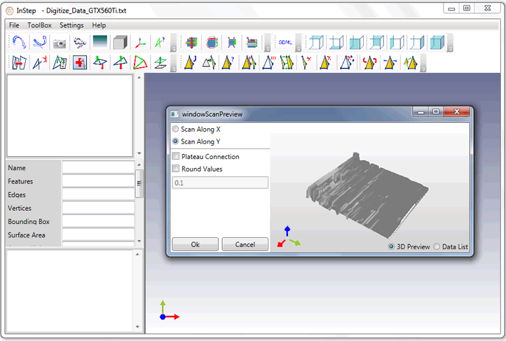
Initially, no preview of the data is available but can be triggered by selecting the '3D Preview' on the bottom of the dialog box. Alternatively, the raw data can be displayed through the 'Data List' option. Depending on the file size, both of these options can take some time to display.
The option to Scan along either X or Y has less influence over the data but can yield slightly different results and should be selected based on how the source data was generated.
The option to round the values to a given value provides an option to make features coplanar, depending on the original setup. Applications that digitize the data will likely generate data with several significant digits included, however the true scan resolution will often fall short of achieving such precision. For this reason, it is recommended to set this value based on what is realistically distinguishable (high feed rate scanning will often have a resolution in the order of 0.1 to 0.5mm, higher if mechanism used to detect a probe contact uses a force generating spring and the target object is not perfectly rigid). On the other hand, some setups can generate very high resolution scans, in which case a value lower that this is perfectly acceptable.
As a default, the application will stitch data points together as it receives them. this means that if data in one row has a different Z component than matching data in the next row, the triangle generated will have a slope to it, transitioning from one Z value to the next. Though this is perfectly reasonable in a number of cases and leads to the lowest facet count, it is sometimes desirable to have flat surfaces only that sharply transition from one Z to the next by means of a step rather than a slope. For these cases, the 'Plateau Connection' option is available which generates additional information so that only sharp connections exist. The downside to this approach is that the amount of data quickly increases (up to 8x) and that there is more chance that the resultant data will have pierced surfaces that provide issues to downstream processes.
Once the desired options have been selected, the application generates surfaces similar to the STL import and the different checks are performed. During the normal course of this input, the issue will be detected that the data does not form a solid. It is recommended that the Inflation tool (only available to Design & FE licenses) is used to thicken the surface into a solid, thereby generating a body that can be correctly exported and used. If surface-only data is sufficient, then this option does not need to be used.