The previous tutorial ended with the export of the block to the Step format. Here we will continue from this point and switch over to the Guided interface. Of course,
if you are just starting the application, it may prompt you for the Interface option, in that case, simply pick the Guided option.
To switch from any interface to the Guided or any other interface, click on the Settings > Interface > Guided checkbox as shown in the figure below:
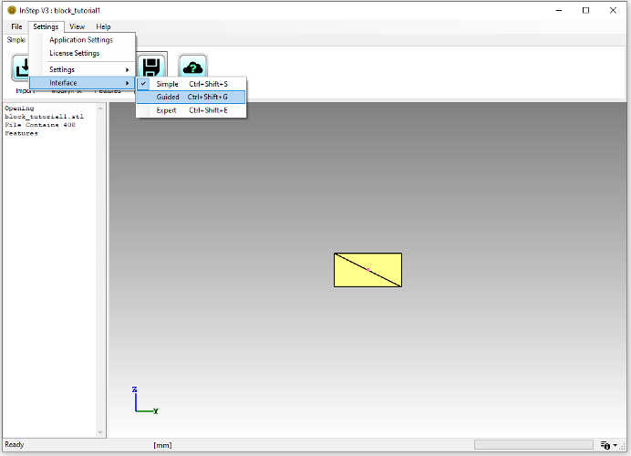 Switching Interfaces
Though it is generally possible to switch Interfaces at any time, it is recommended to do so only prior to loading and working with a file as
changing at a later stage may introduce changes that the application may find difficult to reconcile.
In general, the Guided interface uses a floating menu to provide the actions to be applied to the loaded data. Entering this process is done by
clicking on the Start button:
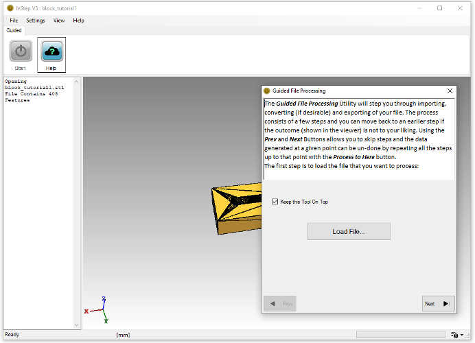 Guided Interface Start Page
The first step in the interface asks to Load a file. Using this is essentially the same as using the File Menu. The file being used for this tutorial
can be downloaded from here:
Example USB Port File (STL)
Note that the floating dialog box will be kept visible/on top if the 'Keep this Tool On Top' is left checked. This is recommended when multiple other applications are
running as it can otherwise disappear and make working more difficult.
Once the import completes (the message box shows that 2192 Features have been loaded, if the Message field is not visible, see how to turn it on in the previous tutorial),
the next step of the conversion is to be defined by moving through the pages
using the 'Next' button or, similarly, moving to a previous step using the 'Prev' button. It is important to understand that moving forwards or backwards through the
options does not change the data, only by using the actual options on each page can those options be applied. If an issue has been encountered, perhaps data being modified
in a way that wasn't desirable, it is possible to revert to the same state by using the 'Process to Here' option which retraces all the steps up to those applied on a given page.
On the second page, the Units are made available with the explanation for this step given in the text above the tool:
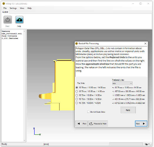 Unit Selection in Guided Interface
This step seems perhaps confusing but it is relatively straight forward: mesh/polygon files such as STL, OBJ, PLY and similar do not contain information about what units the data represents.
The locations of features are simply values, but what a value of 1.0 represents (1.0 millimeters, 1.0 meters, 1.0 inches?) is not defined by the file. This page provides both
the option to define what the original file values represent as well as what the user would like to use as their most comfortable (preferred) measure of unit.
On the left, the page provides the bounding box size (a box that is aligned with the X/Y/Z coordinate system and fully encloses the loaded body) and
assigned to that, a unit. On the right, the corresponding box size is given, for the Preferred units selected from the drop-down box above. One of the lines
will always be the same on both the right and left sides. In this example, the bounding box size has been found to be 15.79 / 10.85 / 14.50 [units]. From experience
we know that this value is in milli-meters (a frequently used unit for these kinds of files). So, the first option (these round selections are called 'Radio' boxes as only one of
them can be selected at a time) is the correct value for this file. If we are comfortable working with the millimeter units, then this is all the information that is needed.
If we prefer something more "imperial", then the inch or feet units are appropriate. Selecting, for example, 'inch' from the drop-down box and keeping the 'File Units' value
on the left at the first, 'mm' entry, we now see that the bounding box of the original data is, in our preferred units, 0.62 x 0.43 x 0.57 inches.
The purpose of this page is to make something fairly complicated a lot easier, but it can be a bit overwhelming at first. What is important to note
is that the Preferred Units being set here are used for a number of tasks, including setting the output units in STEP files and indeed in all numerical
processes applied by the application. Getting the units right is also very important as this affects tolerances and other items. The application uses approximations
for finding locations that are close to each other and therefore it is important to know whether two items are, for example, 1 millimeter apart or 1 meter. In most
cases, the recommended approach is to not apply scaling factors (can be requested through the 'Do not Scale Data' which locks the import to the output unit) and then
to apply any scale required only within the CAD application that is to work with the resultant files.
For the purpose of this tutorial, we will use a preferred unit of 'mm' and set the 'Do not Scale Data' which automatically locks the import
units to 'mm'.
Clicking Apply performs the conversions, in this case, the size does not change. Note that with this example, the there are two visible 'Triads' in the viewer:
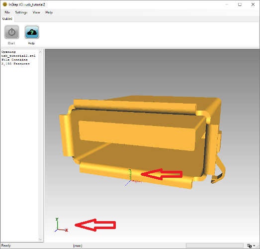 Global and Unit Triads
The one in the bottom left corner of the view is considered a 'global' triad and will provide information about the orientation that the part is in. It is a helpful
tool for cases where orientation of the part is not obvious. It can be turned on/off using the Alt - 'T' shortcut.
The second item, located on the curved surface of the USB connector, is a 'Unit' Triad. It shows the origin of the data (the 0/0/0 coordinate point) as well as what
one unit looks like relative to the data. From this we can see that the bent section at the bottom measures about 1mm which again, makes sense from an experience perspective.
The primary use of the Unit Triad is to give a feeling for the size of the body being imported. If the units are, for example, set to 'mm' and the body being imported is a
vehicle yet appears only slightly larger than the unit triad, then the scale is likely incorrect. The unit triad can be disabled using the Settings under View or through
the shortcut Alt + 'O' (for Origin).
Moving on with the Guided Process, we come to the page for Error corrections:
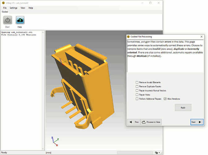 Basic Error Correction Options
The options we are going set here are the Removal of Invalid and Duplicate items as well as correction of Normals. Error correction is one area that is receiving continued attention
with future released likely providing additional tools and options. For now, only these options are applied here. The Invalid Elements option looks for triangles
that are defined in such a way that they do not have an area (either two corners being the same or all points on a straight line). The Duplicate Facets option also looks for
Triangles (facets) that contain the same three corners, though perhaps not in the same order. Repair of Normal Vectors iteratively looks at neighboring triangles and 'flips' any
that have an angle larger than expected. The orientation of these Normals (the direction pointing away from the surface of the body) is important as other processes rely
on them being correct.
Upon pressing Apply, the application checks the data and performs any corrections. It is to be noted that the Message panel on the left (see Tutorial 1)
provides some feedback about items that have been checked/detected. In this case, 0 features are removed as part of this step. Though the body does not actually
contain problematic items, it can be prudent to run these basic checks to verify this.
In addition, the application also informs about the 'Splitting Body' operation which resulted in 1 Body. During the repair step, irrespective of
what options have been selected, the application checks to make sure that any individual bodies have been separated and are independently represented.
This step is important as other processes perform their tasks on a per-body approach, so if multiple bodies are combined into one file, then they need to
be separated so that there is no confusion as to what component belongs to what body.
Clicking Next (or alternatively, the 'Process to Here' first if any changes are to be reversed), brings up the Feature Detection page:
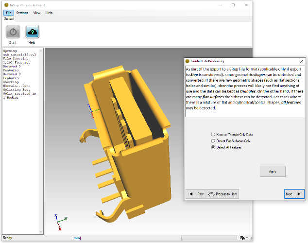 Feature Detection Options
This page defines the level to which the application should attempt to convert the triangle data into more advanced features. The first option, Keep as Triangle-Only Data, is
not going to perform any conversions and is essentially the same as skipping this page. The option to Detect Flat Surfaces Only, allows surfaces that are oriented in the same
direction and connected to each other to be combined in such a way as to be represented by their boundaries only. The last option, Detect All Features, attempt to
find and represent flat, conical and cylindrical surfaces.
For the purpose of this tutorial, Only Flat Features are to be detected. Clicking Apply, the resultant data is generated:
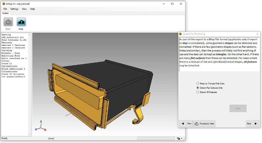 Feature Detection Showing Errors
The result of this is not as expected. For one, interior surfaces (those that are in dark grey) are visible and exterior surfaces appear to have been deleted,
exposing the interior. The application does not report issues, indicating that the process completed as expected.
The issue here is one that was briefly mentioned before: tolerances. The default setting for the application is to use an Edge Length based tolerance,
set to 0.5x the minimum edge length. In this case, the value leads to surfaces becoming collapsed, exposing the interior.
For now, there is no way around this, and the process would likely best be completed by reverting the changes (Process to Here) and then to choose the Keep as Triangle-Only Data
which does not perform the feature detection. For this body, the way to circumvent the default tolerance methods (which are available through the Expert interface and
shown in later tutorials), is to use the unit system to better represent the data, so that the tolerance is more appropriate. Going back to the units page, the Preferred Units
are set to Meters ('m') and the changes applied. Looking at the Unit Triad shows how small the part is relative to the units. Working through the next page, the Invalid and Duplicate
features are removed and normals corrected (with the same results). Now, on the Feature Detection page, selecting All Features and clicking
Apply, results in the data shown in the figure below:
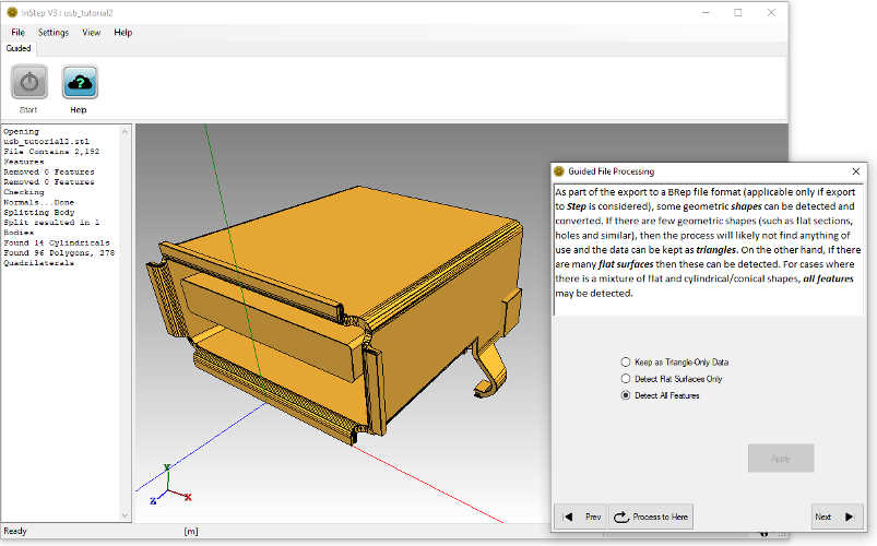 Feature Detection Successfully Completed
Again, the Message Panel shows what the process found and converted. It may appear that there are still 'too many' items that have not been properly
converted, however, upon closer inspection, it may become apparent why these items were not correctly converted. Several items with complicated boundaries
cannot be properly converted to a geometric representation and are therefore left in their original state. Other, simpler surfaces are correctly converted.
With the processing of the data completed, the remaining step is to export the file using the Save As option on the next page. The process and options available
are the same as previously discussed.