Auto Generate Seed Mesh
Time to read: ~6 min
The Auto-Generate option for the Seed Mesh is an easy to use and relatively fast option to generating the Seed Mesh, whether as the
only step or as a starting point for a refined and optimized mesh.
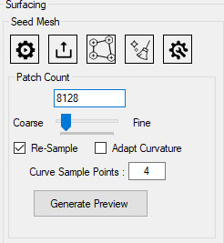
The process is started by clicking on the Auto Generate Button in the Seed Mesh Group
 : Auto Generate Seed Mesh
The definition of the Automatic Seed Mesh consists of:
- Defining the approximate number of Patches
- Determining if the original data is to be Re-Sampled
- Defining the number of points to be sampled between corners
 Initial Slicing Tool Environment
Approximate Number of Patches
The Patch Count field defines the target number of patches to generate. By default, upon launching the tool,
it will interrogate the original number of faces in the body and set this number to 10% of the range between the minimum
allowed and maximum allowed above the minimum allowed. The minimum allowed the larger of 100 or the number of faces divided by 200
and the maximum allowed is the smaller of 100,000 or the number of faces divided by 2.
In general, the number of patches needs to be understood to be a function of the complexity and desired detail. The initial guess value
can be a good starting point, but this value has a large amount of influence over how fast the process works and how accurate the result is
in terms of approximating the original data.
To make changes to the value faster, the slider can be dragged between the limits. Manual input of a value is also possible though it cannot be set below
or above the maximum.
Re-Sample
The option to Re-Sample the data is important in the context of what the process consists of. During the determination of where the Patches (the corners of the
seed mesh) are to be placed, it requires information about what defines the original data. For the case where the data is a non-solid set of surfaces (often obtained
from 3D scanners where only part of the body has been scanned) then re-sampling will artificially try to close the data into a solid, something that should be avoided
(for this reason, if the application determines that the body is not solid it will turn off the Re-Sample option by default). If on the other hand, the
data has been scanned in a highly detailed fashion and pre-converted into a solid body (so no gaps or overlaps exist), then the data is likely already well defined
in all regions and re-sampling is not necessary (as it would only recreate what the scanner has already provided). The case where re-sampling is of use is
for cases of varying mesh density, with regions that have a high level of detail and other regions where large triangular surfaces are being used. In this
case, the resampling obtains a more uniform mesh that allows for better placement of the patches.
It is left up to the user to compare the two cases and apply judgement as to whether resampling of the data is of benefit. In general, resampling takes more time
but should lead to a more uniform result and is likely also the more consistent option for unknown meshes (and thus the default for solid bodies).
If the data is re-sampled, the Settings allow for changes to the level of resampling to be applied.
Adapt Curvature
This option is not considered a default setting but provides a way for the mesh to become more (though not completely) aligned with the curvature of the source
body. The internal process consists of detecting approximate curvature within the original mesh and then to move the resultant data closer to whatever locations
were detected. The threshold of what is considered a curvature location can be modified from the Settings by changing the CurvatureThreshold value. A value of 0.5
here means that any curvature that is above the average will be considered whereas 1.0 indicates that only the highest possible value is to be considered. A value of
0.0 essentially has no effect as any location will be considered a curvature target location.
Curve Sample Points
The number of samples obtained from the original surface is set by this (very simple) value. It defines how many additional points are considered between any two
edge end points in the patches. What this means is that once the Seed Mesh (set of Patches) has been obtained, it internally considers their edges as straight lines that
are to receive this many additional points, equally spaced along the original line. These points are then projected onto the original surface and thus
re-sample the original mesh at this location as a way to represent the NURBS Surface data (by means of generating the inverse calculation of knot locations).
Beyond determining how well the original surface is being approximated, it also defines the highest Order that the NURBS surface can be defined by.
Each NURBS Surface has an Order along their U and V coordinates. The highest Order is defined by the number of points (+1) that define the underlying curve.
Therefore, in order to obtain a Cubic NURBS Surface (the recommended value), at least 4 points need to define the curve or 2 additional points need to be inserted between
the corners. A Linear NURBS does not require any additional points and a Quadratic NURBS requires at least one internal point. A Quintic NURBS (the highest offered)
requires at least 4 internal points (the default). Keep in mind that this only defines the highest Order possible, not the Order that is actually being used (this is set
in the Generate Group, prior to converting the data).
Generate Preview
Once the options have been set, the Automatic Seed Mesh process is started by clicking the Generate Button. Several of the internal processes required to obtain the
Seed Mesh are not easily evaluated for their time requirement and thus the progress status may seem frozen for short periods of time. This is by design as
calculating in advance how many iterations will be required of each process would greatly slow this down and therefore the updates are provided as
different tasks get completed. The duration depends on the size of the original data, the target number of Patches and the options applied to them.
In general, the process is quite fast and should provide a Seed Mesh for a reasonably sized model within a matter of a few seconds to a few minutes. If
this takes longer, check that the Settings are not set outside of their recommended values, that the source and target sizes are not beyond a reasonable size
(original data should consist of 10's to 100's of thousands of faces, millions are possible but considered Large; target Patch Count should be on the order of hundreds to thousands, Sample points should be below 10).
Once the Seed Mesh generation completes, a preview will be placed over the original data. In order to keep the preview mesh as lightweight and fast as possible,
some approximations are in place that make it look like the edges dip under the original surface. Though this may be correct, the error should be very small if there
the seed mesh is not on the very coarse side. Consider this an approximation. In order to get a better view of the seed mesh, it is possible to hide the source faces
(using the keyboard short-cut Alt+F).
Show Problem Corners
Once the Seed Mesh preview completes, this option (may) become available. Turning this option on will show locations where the mesh encountered questionable
quality, with the location closest to the corner being identified. Frequently, it will be necessary to turn off face visibility (Alt+F) to better see these locations.
It is recommended that any such locations be observed for strange behavior or self intersections (which may need to be manually resolved by using the seed-mesh
export, import options together with an external mesh editor).