NURBS-Relief Tool
Time to read: ~2 min
The NURBS-Relief Tool is a specialized tool that is intended to help with cases where a scan or a relatively flat surface or similar is being used as a reference for work
such as mold design, sheet metal or fiberglass tooling.
In these cases, the normal workflow has problems getting a suitable body stitched together and simplifications will fail to properly maintain the boundary or similar.
Introducing the NURBS based Relief tool!
Pre-Requisites
The data being imported must generally be flat (within a percentage of the bounding box size, which can be set from the properties).
Additionally, the data should lie in the X-Y plane (slight alignment outside of this can be tolerated, but errors may arise) and must represent a single body. If the general requirements are met, the application will
detect that the data is suitable and enable the "N-Relief" tab.
Workflow
The intent is to keep the process as simple as possible:
- Open the Definition Tool by clicking on the corresponding button (see below)
- Start with a coarse grid and an average number of sample points. 10x10 grids with 5x5 samples usually work well.
- Leave the Continuous option off, degree at Cubic, Auto Normals: on, Thickness to 20% of the edge and Extend Perimeter:On.
- Click the Preview button
- Turn on Edges (Alt+E) and inspect the result.
- If everything looks fine, export (on the current tab) to a STEP file
- Optionally, evaluate what a larger number of grid points and samples do. Increase the number gradually, try to keep the total number (gridX * gridY * samplesX * samplesY) below 40,000; grids of 20x20 with 5x5 samples usually do fairly well.
 Definition
Clicking this button brings up the dialog where the resolution and options are set. This is required to enable the preview, mesh and export options.
On the pop-up dialog, the following options are available
- Divisions X, Y
- This sets the number of Grids along the X and Y coordinate. Effectively, this defines how many surfaces are generated across the source data.
- Samples X, Y
- This defines how many samples are to be added within each Grid. Making this larger will result in more detailed representation at the expense of a larger file and slower execution time. The Divisions x Samples should be on the order of 10 to 200 for best performance. Values above these may exceed computer resources.
- Make Continuous
- If turned on, the algorithm will overlap neighboring patches, generating a smoother (tangentially continuous) set of surfaces at the expense of larger files and possible over-smoothing. If turned off, the option exists to export the data to a Mesh Body, with it turned on, only STEP files are possible.
- Max Degree
- Highest curve degree. Generally, Cubic splines are to be used as they offer a good balance between detail and size.
- Normal / Auto Normal
- If set to Auto, the application will attempt to generate the best Normal vector from the data (should be in the +Z direction), alternatively, the value can be manually input.
- Output Thickness (Abs/Bounds %)
- The output is a solid body that needs a thickness. This can be an Absolute value or a percentage of the longest side edge
- Extend Perimeter
- Often, the source data is not exactly aligned with a square box aligned in the X/Y plane. Turning this on will attempt to expand any sides that are not exactly in the plane. It is possible to see a preview of what this extension will look like. If the output does not meet the expectations, external modification of the data may be necessary.
 Height Map Definition
As the primary purpose of the Nurbs-Relief tool is to take thin models with little thickness along the Z coordinate and no bounding definition, other possibilities are available too.
One is to use a simple flat surface (consisting of only two triangles - though more are possible) to define a flat surface as a starting geometry. By using what is referred to as a Height Map
(or Displacement Map) as an alternative way of defining the height of the geometry relative to a flat base, a 3D representation of an image can be produced.
This is the purpose of having an import option for an image that defines this height map.
Steps to use a Height Map
- Import a flat surface file (one that measures 1x1 mm is available here as a starting point, you can modify it using the Edit tools)
- Switch to the N-Relief Tab
- Click on the Define Button to set a starting point for the grid resolution (ideally start with fewer Divisions and fewer Samples: 10 and 5 respectively are a quick starting point)
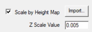
- Check the "Scale by Height Map" box and pick the image file from the "Import..." button
- Set a Z Scale Value that defines what effective height a fully white pixel represents (Black is 0, White is 1 and gray scales are values in-between)
- From the Main application page click on the Preview button and optionally turn on Edges (Alt+E) to inspect the result.
- Gradually make changes to the settings until a suitable resolution is found. If necessary, scale or crop the image in an image editor to match the desired shape. Keep in mind that the boundary of the
image is automatically set to a black pixel so as to maintain continuity with the geometry; if ncessary adjust the image appropriately.
- Once happy with the preview either convert to a Mesh (only available if the "Make Continuous" is left unchecked) or directly export to a STEP file (NOTE: only exporting from this Tab page will result
in a direct NURBS patch conversion)
 Preview
Clicking the Preview button will generate the data based on the most recent definition set. The preview can be visually reviewed for issues and mesh resolution. With the preview completed, the other options (where applicable) become available. Note that the Make Continuous option will introduce mesh overlap that isn't present in the output STEP file.
Edge visibility can be toggled with the Alt+E keyboard shortcut.
 Convert: To Mesh
If the definition does not use the Make Continuous option, then the data from the preview can be converted to a facetted body that is then available for the other options within the InStep application.
 Clear
Clear
This clears the data and resets the view.
 Save STEP
Once a preview of the Relief is available, the body can be exported to a STEP file. It is important to note that the export option on this tab is different from the main Export tab and that leaving this tab will clear the generated data.
Exporting here generates an output file that considers that the data is of a specific format and optimizes it.